
It is not difficult to suspect that the triac burned out in the washing machine - the machine freezes, does not turn on, or works with obvious failures. But it is impossible to be 100% sure that the radio element is broken since other electronics malfunctions also manifest themselves with similar symptoms. To confirm the diagnosis, it is necessary to carry out a comprehensive diagnosis of the washing machine control board.
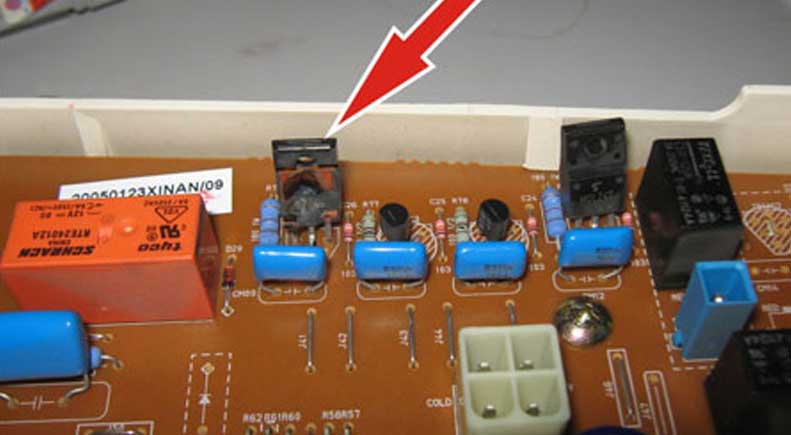
The electronic module should be dismantled, inspected and having found the triacs, begin testing them. Let's figure out what to do and in what order.
Before repairing and replacing the triac on the control board, you must make sure that the semiconductor is faulty. You can test a radio element in different ways. The following verification options are most used:
The most popular way to diagnose a triac is to dial with a multimeter. This tester, unlike the transistor one, is available to almost everyone and is quite easy to use. It is more difficult and longer to assemble a test bench for a one-time check or to organize an electrical control circuit. It is better not to complicate the task and give preference to the tseshka.
Before diagnosing a triac, it is recommended to understand its design and principle of operation. From an electrical point of view, it is a semiconductor that opens and closes to allow current to flow, much like a thyristor. But unlike the latter, this radio element consists of two crystals connected in parallel, which allows it to conduct current pulses in both directions. Due to this feature, it is widely used in systems with alternating voltage.
The triac can fail for two reasons:
Even a professional electrician will not detect a problem with a triac without a dial tone with a multimeter - visually everything can be clean. To make sure that the semiconductor is malfunctioning, you will have to ring it with a buzzer and measure the resistance at the contacts.
Before proceeding with direct testing, you should decide on the diagnostic method. Two options are practiced: either solder the semiconductor and check it separately, or take measurements immediately on the board. The second method is simpler, more convenient and safer: there is no need for unnecessary manipulations, which reduces the likelihood of errors and aggravation of the situation. But there is also a drawback - the overall performance of the module will invariably affect the results, knocking them down.
Having prepared the triac and multimeter, you can proceed to the diagnosis. At the first stage, the transition is checked for breakdown: the probes are applied to the power electrodes, and the result is evaluated. The appeared "0" will indicate a malfunction of the element. If “1” is displayed on the screen, then the semiconductor is in working condition. Some modern testers show “OL” instead of one, which also indicates the performance of the part.
The second step is to move one of the probes to the control contact to measure the resistance between them. Normally, the indicator should vary by about 100-200 ohms. After the clamp clings to another power electrode, which will lead to the display of "1" on the screen.
Next, we check whether the transition of the radio element opens. To do this, quickly touch the probe to the control output while applying current to the remaining contacts. The latter can be achieved by using an additional wire or by placing the tester clip diagonally. If the triac is working, then the indicator on the multimeter screen will change - instead of one, another number will be displayed. It is important to be extremely careful, since the semiconductor will not last long in the open state due to insufficient voltage.
If during the test it turned out that the soldered triac is working, it means that another element of the control board causes a failure. For complex diagnostics of the module, it is better to contact the service center.


Copyright © 2020 Coimbatore Service.