Repair of the electronic module of the LG washing machine
Specific skills and knowledge are required to repair the washing machine control board. If you have never seen a microcircuit and did not hold a soldering iron in your hand, then it is better to entrust this work to the master. However, if you have some experience, you can try to cope with the task yourself.
Repair of the electronic module of the LG washing machine is carried out in two stages. First, you need to remove the board and find the burnt element. The second step is to replace the semiconductor. But first, let's take a look at the nuances.
Which part is responsible for what?
Looking at LG's CMA control module for the first time, one might be surprised at how many semiconductor elements it contains. Checking each one will take a lot of time, so you need to understand which sensors are responsible for what. Then it can correlate this information with the breakdown symptoms and quickly detect the defect.
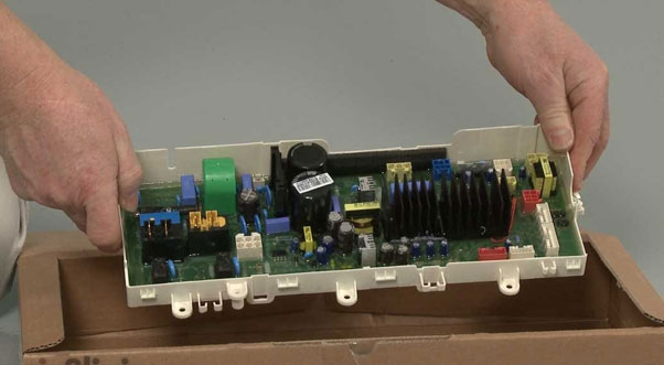
In general, the LG automatic machine module consists of two parts. That is a control panel and a power unit. Next, will disassemble the part to get to the board itself. Semiconductor elements locate under the casing and the compound, which control the operation of various SMA units.
Therefore, to not check every semiconductor, think about what exactly you did not like about the operation of the machine. For example, if it stops turning on, you must test the sensors responsible for powering the device. Likewise, if problems are with the inverter motor, pay close attention to the HS1 power assembly used to control the drive motor. Let's deal with everything in order.
On the left of the control module are the elements responsible for powering the machine.
- integral stabilizer KIA7805, on the board it is designated U14,
- pulse converter based on PWM controller STR-A6059M,
- mains rectifier and filter (designated BD1 and CE4),
- protective varistor (Z2),
- mains fuse,
- key converter chip (designated U12),
- pulse transformer SMPS,
- diode D13, capacitor CE2,
- diode D11, capacitor CE8, power supply channel 9V,
- diode D12, capacitor CE9, power supply channel 12V,
- diode D14, capacitor CE6, power supply channel 12V,
- diode D6, zener diode ZD1, transistor Q1, resistor R103,
- resistor R74, aka 205,
- optocoupler U15, transistor assembly U3,
- U13 processor,
- relay X1 (it also connects in series to the heating element circuit),
- integrated voltage regulator 5V, marked U.
The next element on the control board is the temperature sensor. That includes semiconductors:
- Pin 4 (TH1) of the RD6 connector,
- Resistor R12,
- 37-foot processor U.
The following semiconductors of the module are responsible for the operation of the heating element:
- Relay X1,
- 64-foot processor U13,
- 1 and 16 leg assembly U3,
- Relay X2,
- 24 leg processor U13,
- transistor Q7.
The module also has a backup relay control channel. Components are optional. We are talking about the following semiconductors:
- 75-foot processor U13,
- resistor R83,
- transistor Q5,
- relay X4,
- second pin of connector BL.
Responsible for the operation of the pressure switch:
- resistors R6, R7,
- 67-foot processor U13.
The next semiconductor block is responsible for the operation of the prewash compartment valve. This:
- 29-leg processor U13,
- 4 and 13 leg assembly U3,
- resistor R25, R29,
- optocoupler U8,
- Triac TR3,
- pin 1 of connector YL4.
The main wash compartment valve is responsible for:
- 31 legs of the U13 processor,
- 6 and 11 leg assembly U3,
- resistor R23, R27,
- optocoupler U6,
- Triac TR5,
- pin 4 of the YL4 connector.
The following circuit controls the hot water inlet valve:
- 31 legs of the U13 processor,
- 6 and 11 leg assembly U3,
- jumper J1,
- resistor R24, R28,
- optocoupler U7,
- Triac TR4,
- the second pin of the YL4 connector.
Semiconductors are responsible for the operation of the SMA drain pump:
- 61 legs of the U13 processor,
- resistor R77, R79, R82,
- transistor Q4, Q3,
- optocoupler U4,
- triac TR20,
- pin 4 of connector BL4.
If there are problems with the CMA hatch-blocking device, pay attention to the following block of elements:
- 27 leg processor U13,
- 2 and 15 leg assembly U3,
- resistor R21,
- optocoupler U2,
- relay X3,
- pin 1 of connector BL4.
The following are responsible for the operation of the Hall sensor, which controls the engine speed:
- Pin 4 and 6 of connector BL6,
- Resistor R44, R60,
- 3,4,5,6 legs of U1 chip,
- 19.20-foot U processor.
If the washing machine motor stops working, test the following circuit:
- 17th leg of the U13 processor - HS1 power assembly (output stages and drivers) - U1 microcircuit,
- comparator from the U11 microcircuit - storage inductor RA - resistor R58, R57,
- 6.7 legs of the comparator U11 - control of the supply voltage 300V, the signal goes through the circuit with the diode assembly BD1, resistor R70 and 41 legs of the processor U.
As you can see, plenty of semiconductor elements are on the board, so repairing the control module can be overwhelming for beginners who need help understanding microcircuits. However, if you have such concepts as resistors, relays, and optocouplers are not surprising, and you roughly understand how circuits is built, then you can fix the unit yourself.
Common Problems
Such a breakdown as damage to the electronic module infrequently occurs in LG washers. Usually, it is not the control unit to blame but some node or sensor. For example, if the machine does not turn on, do not immediately disassemble the board - first check the socket, power cord, plug, noise filter, and start button.
However, the problem will be in the control module in rare cases. We will tell you how the board is checked for certain breakdowns of the SMA.
- The washing machine does not turn on, while the indicator on the electronic module is on. First, the turn-on signal circuit is checked whether it arrives after pressing the button on the 63rd leg of the U13 processor (through the U15 optocoupler and pins 13 and 14 of the U3 assembly). If everything is fine, the 9V power channel is tested, and they look to see if the specified voltage goes to the X1 relay winding.
- The machine turns on, but the LE error is displayed while the engine is running. Usually, such a malfunction is caused by damage to the Hall sensors and their circuits. You must check and replace the current limiting SMD resistors on the module. First, you need to remove the compound on the block of tachometers.
- The washer turns on, but the motor does not run. In this case, the error PF is on display. Typically, such a breakdown is associated with a lack of a 300 V power supply on the HS power assembly. First, the integrity of the FUSE1 fuse is checked, and then the semiconductors of the BD1 circuit - the HS1 assembly - the R70 resistor for 41 legs of the U13 processor.
- If, after turning on the CMA, a CE error appears, it means that there is an overcurrent in one of the output stages of the assembly or a defect has appeared in the control circuit (resistor R58, R57, pins 6 and 7 of the U11 comparator on the 17th leg of the U13 processor). Then you will need to replace the HS assembly. It is also worth checking the integrity of the engine windings, and the matter is in inter-turn short circuits.
- The machine turns on, but the cycle does not start due to a de error. That means that the hatch door is not locked. The serviceability of the optocoupler U2 and all elements of its circuit (connector BL4, resistor R21, 27 legs of the processor U13) is checked.
- If the washing machine refuses to drain the water, while all possible blockages of hoses, sewers and pump failure exclude, a block of elements test: resistors R77, R79, R82, transistor Q4, Q3, optocoupler U4, triac TR.
Before testing the control module, ensure the matter is not in the failed SMA nodes only when the breakdowns of other parts rule out. Then, start diagnosing the control board. It is unnecessary to check all semiconductors, but only those that correspond to the symptoms of the malfunction.
Checking and replacing a defective element
Checking and repairing the CMA control module is complicated because the board contains compounds. In addition, often, the block is protected by a casing, which also needs to be removed. Action algorithm:
- Run a slotted screwdriver along the inner perimeter of the casing to clean the sealant from the edges of the board,
- Deepen the groove along the perimeter of the module in the gap between the board and the casing,
- Stick a thin screwdriver between the casing and the control board in the corner where the main transformer location. Gently lift the unit and pull it out of the casing. Be careful not to damage the chip,
- After removing the board, remove the remaining sealant from it,
- Repair the desired section of the board (usually, a damaged semiconductor element is soldered and replaced with a similar one),
- Cover the area with a protective varnish, for example, Plasik70 (for installation work).
For example, a specialist understands that the problem is in the semiconductors responsible for the operation of the drain pump. So, he cuts a hole in the lower right corner not to remove the casing. That makes it possible to test the desired elements.
Working with the LG CMA electronic module with extreme care is necessary. When removing the board from the casing, there is a high probability of damaging the microcircuits. Therefore, if you are not confident in your abilities, giving the washer for repair to a service center is better.


